Reverse engineering a vending machine
Posted on 2015-03-25
So we got ourselves a vending machine. As we want to build our own control unit, some reverse engineering is in order. In this post, I'm not just going to state the results, but also describe in part the steps we took to get there. The fun is in figuring these things out, so I hope to share some of that here.
The snack machine consists of several parts:
- A sliding door that separates the inside of the machine from the outside, probably to prevent vandalism. Once a customer has bought some item, it slides open just enough for them to take it out.
- A stack of drums, which contain the items to be sold. Each drum has its own door which can be unlocked individually, so the customer can only take out the item they just bought.
The control mechanism for the door is relatively straightforward: There's just a couple hall sensors to determine its position and the motor contacts. Not much to do here.
The drums, however, are much more interesting. Each drum contains a motor to rotate the drum, a solenoid to unlock the drum's door, a light barrier to measure drum rotations and, again, a couple of hall sensors. The machine contains more than 10 of those drums and is designed to be equipped with a variable number of them, so wiring up everything directly would be madness.
The manufacturer thought the same and came up with a bus system. However, this being the late eighties, they built their own. While the documentation contains a description of the system, it's a little inconsistent. It also doesn't describe the state machine used by the control unit to implement drum rotation etc., so we began some "informed" reverse engineering of the drum control bus.
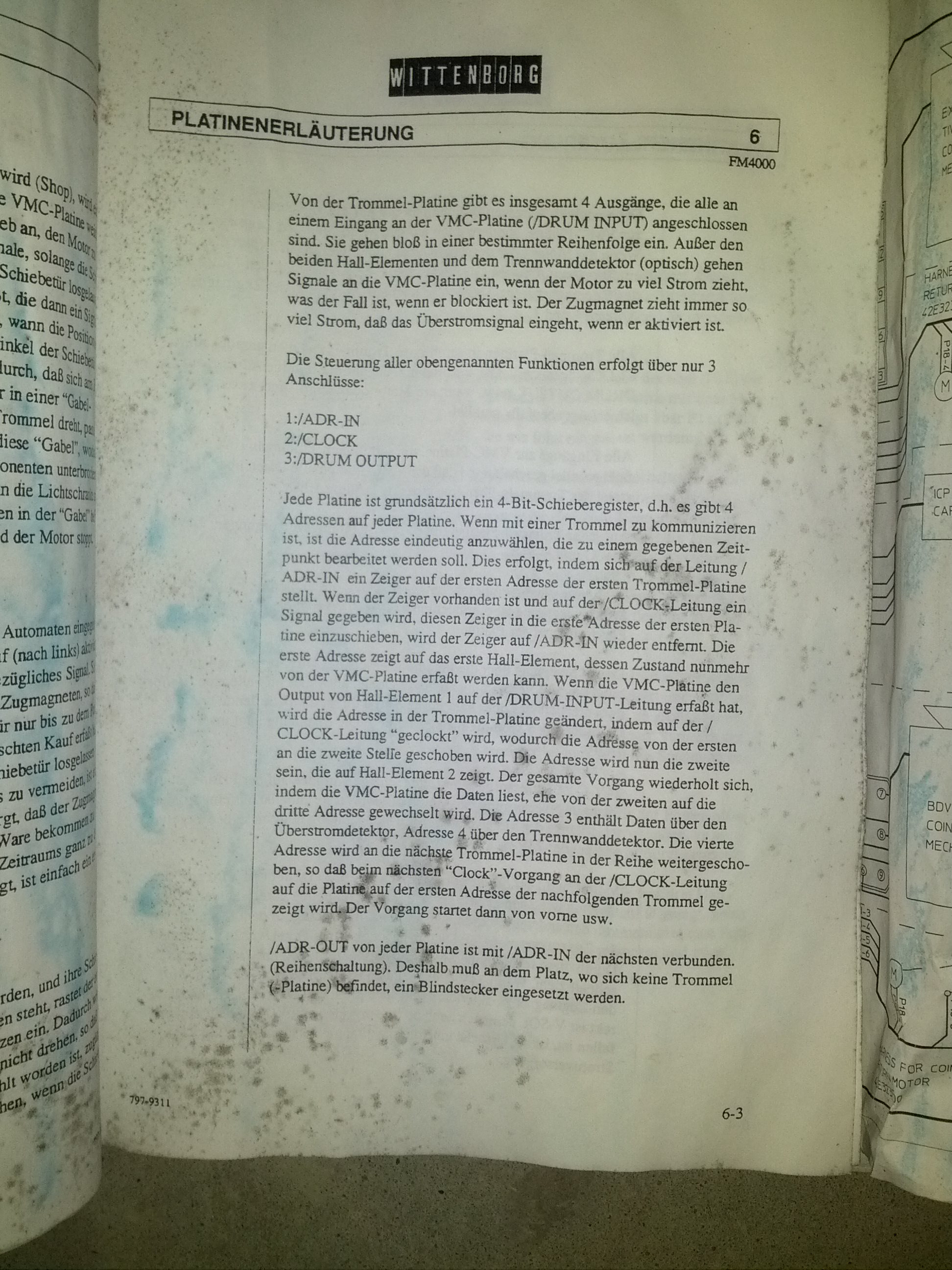
Each drum is a 4 bit shift register, which has its input connected to the output of the previous drum (or the control unit in case of the first drum). All drums share a clock and a data input line (called DRUM_IN), as well as an output line (called DRUM_OUT). The manual doesn't say, but it turns out this line is a open-drain wired-or.
Surprisingly, the machine uses 24V for everything (the solenoid supply uses 40V, but that doesn't concern us here). This is nice, as we don't have to deal with mains levels anywhere, but it means that all the logic levels are 24V as well. I guess this is mostly a safety (accidentally shorting the data lines to supply won't kill the circuit) and noise immunity thing. Sadly, this means that we can't simply attach a logic analyzer to all lines and sniff along (our logic analyzer tops out at 5V). Of course, we could simply add some voltage dividers and then attach the LA, but we weren't certain that the machine would strictly adhere to its specifications (or that the specifications were correct at all), so we chose to err on the safe side and do some preliminary analysis using an oscilloscope (after checking with a multimeter that the levels at least averaged at some safe value). This is how the setup looked like (*ahem*):
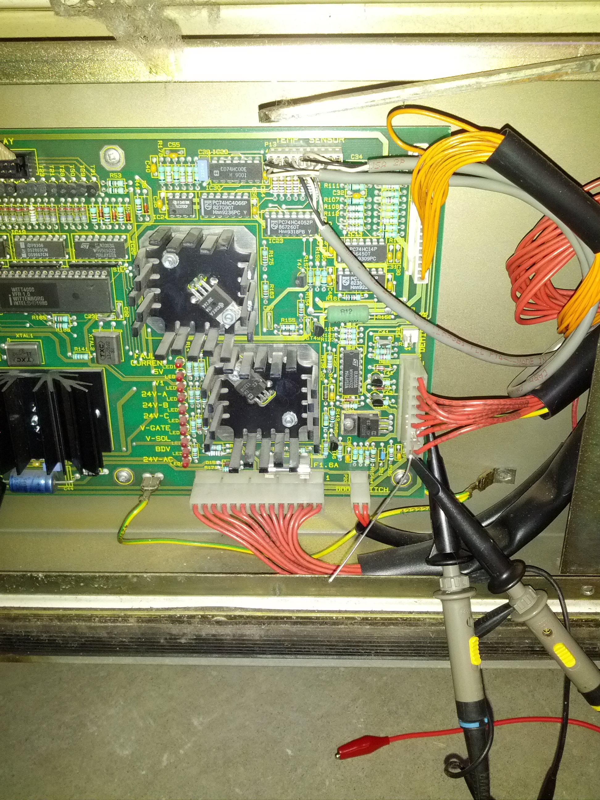
Unfortunately (but as one might expect given such a dirty setup), the measurements were quite noisy. Also, we could only watch 2 channels at once, which made it very difficult to figure out what was going on. We were, however, able to confirm that the logic levels never exceeded 24 volts.
The logical next step would have been to just add some voltage dividers and attach the logic analyzer, but that would have meant getting up and walking to the neighboring building, so we asked ourselves if there was anything else we could do while we were still here.
We were also curious how the drum control boards looked like. It couldn't be anything fancy given when the machine was built, so we removed one. Turns out that they are very straightforward:
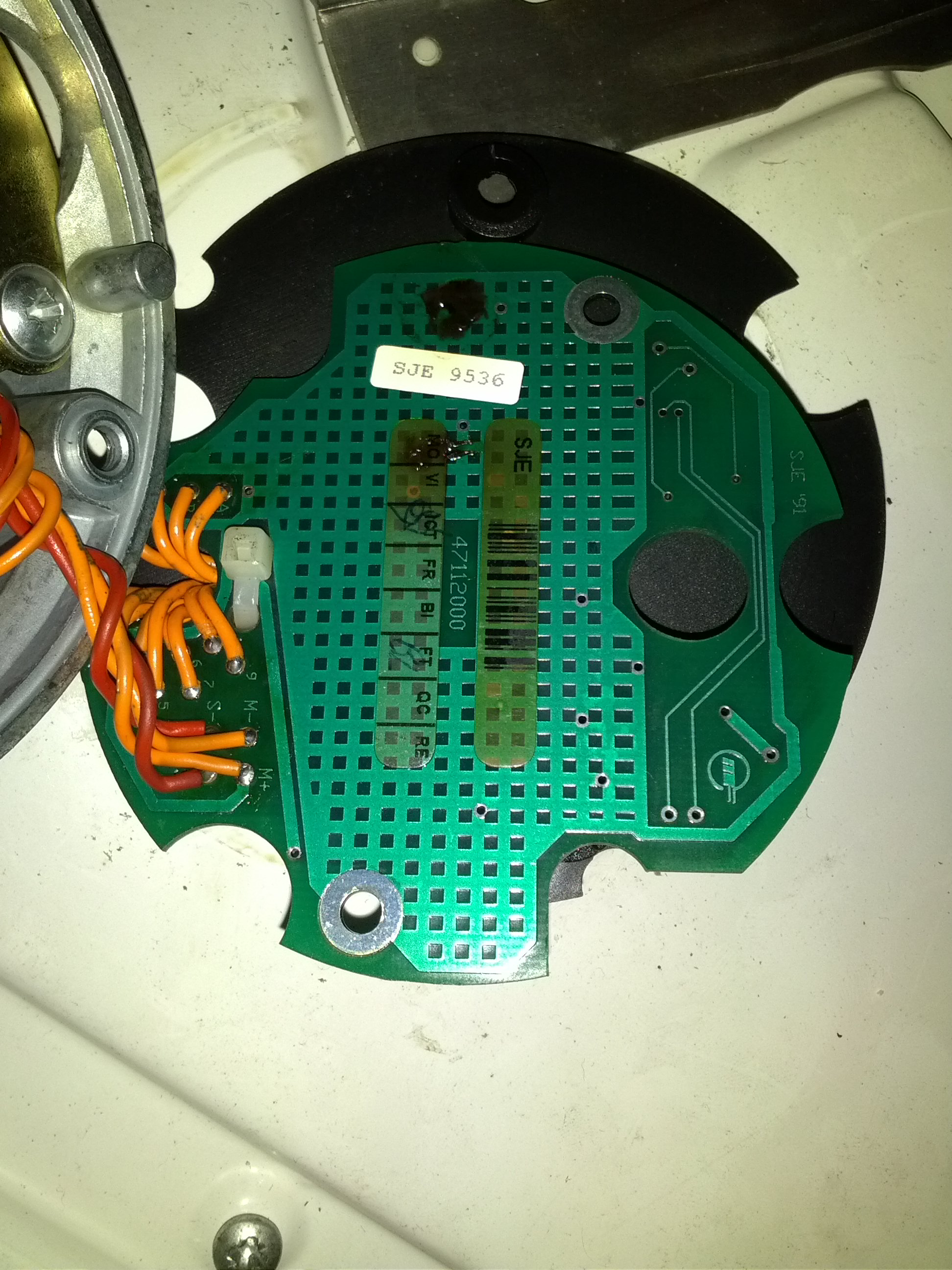
Today, you rarely see an effectively single-layer board populated with standard discrete components in any kind of appliance anymore, so we were pleasantly surprised. Rather than looking at signal traces and emulating them, making informed guesses as one would usually do, this allowed us to simply plot the schematics, look up all the components and have a definitive reference on how this board will behave in any situation.
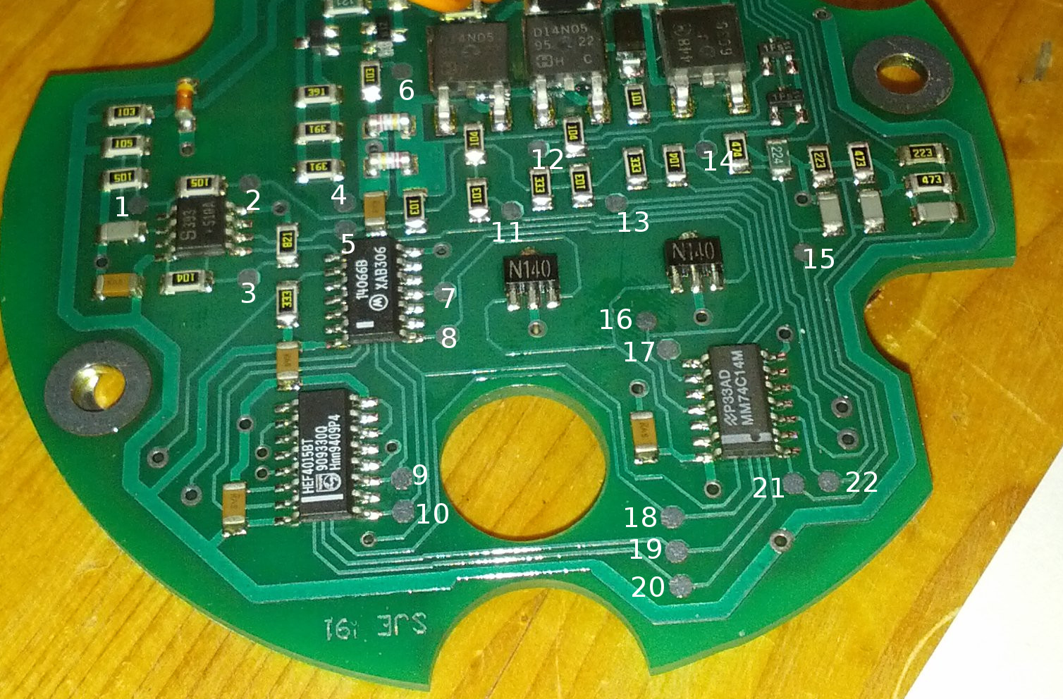
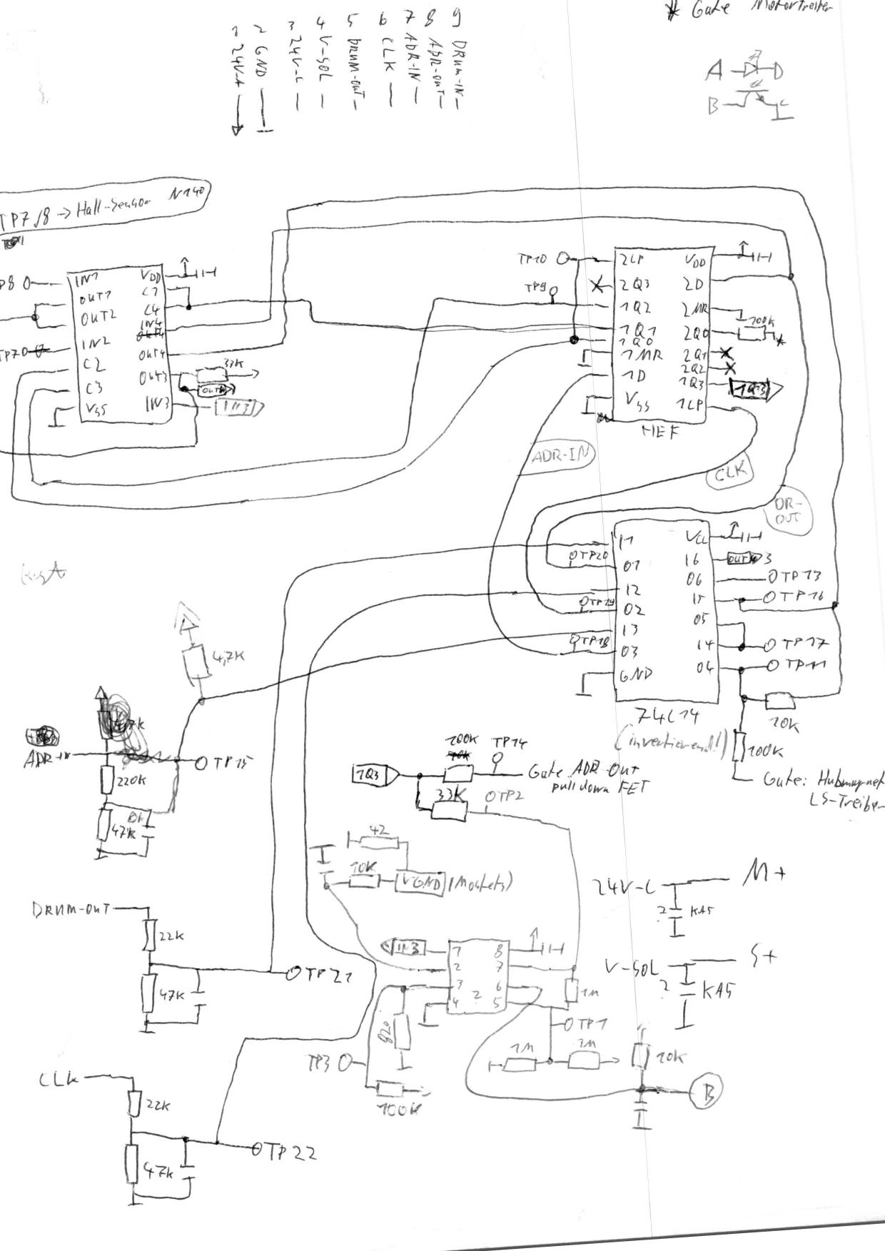
The first image contains the test point numbers used in the schematics. The schematic is the complete result of applying a continuity tester to the whole board. As it was drawn incrementally, it's not very readable. A fellow Entropian (with a much cleaner handwriting) redrew the most interesting parts of the schematic later:
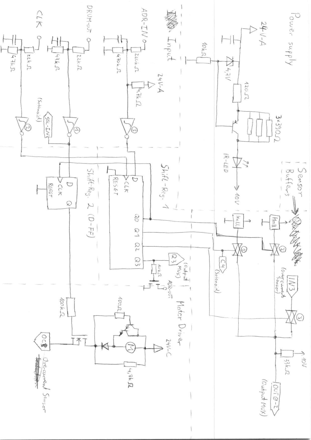
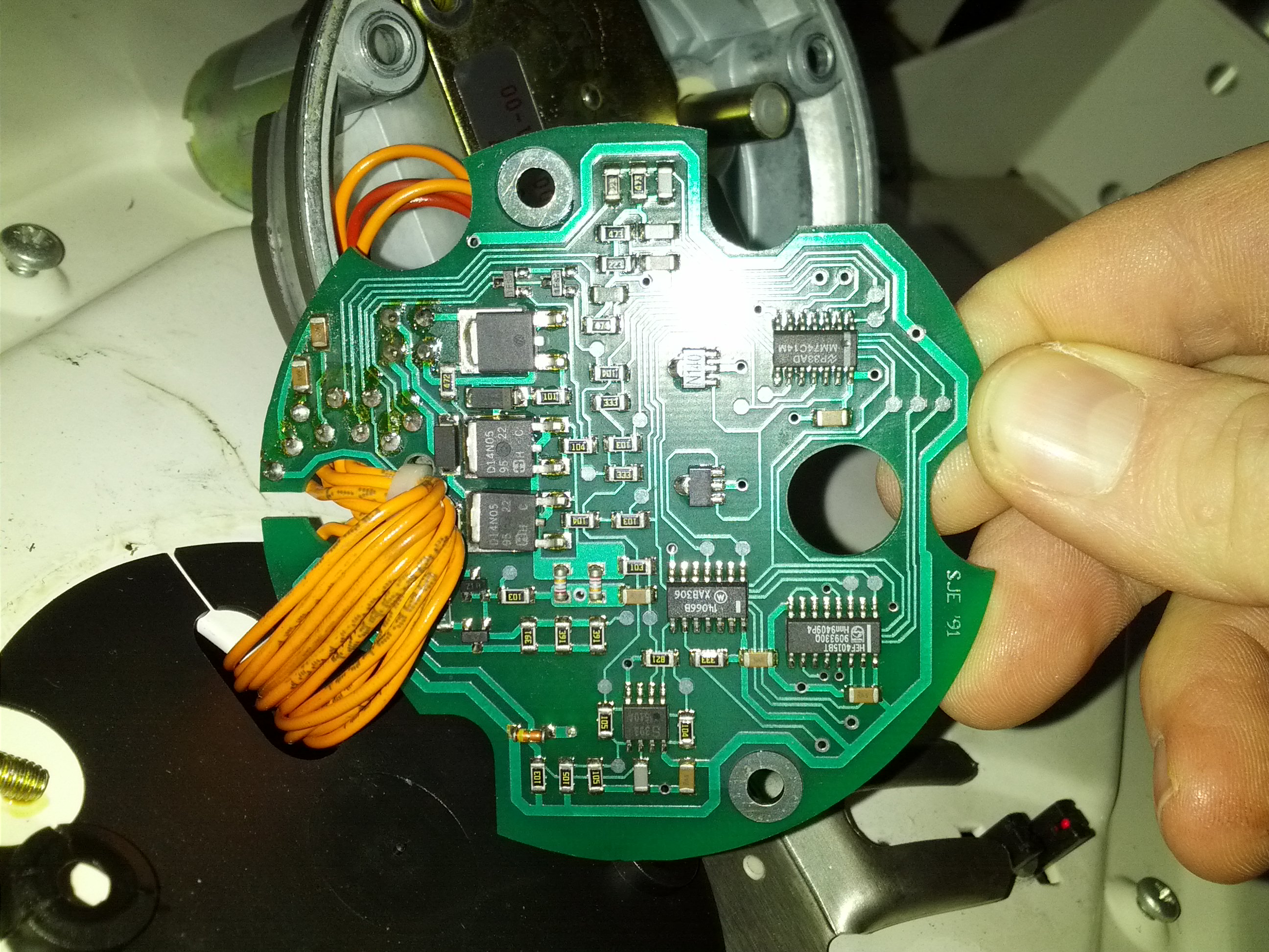
I invite you to think through it yourselves. I'll just point out some of the interesting parts:
- The second shift register of the HEF4015B is abused as a flip-flop
- The construct with the Darlington transistor probably serves to actively break the motor
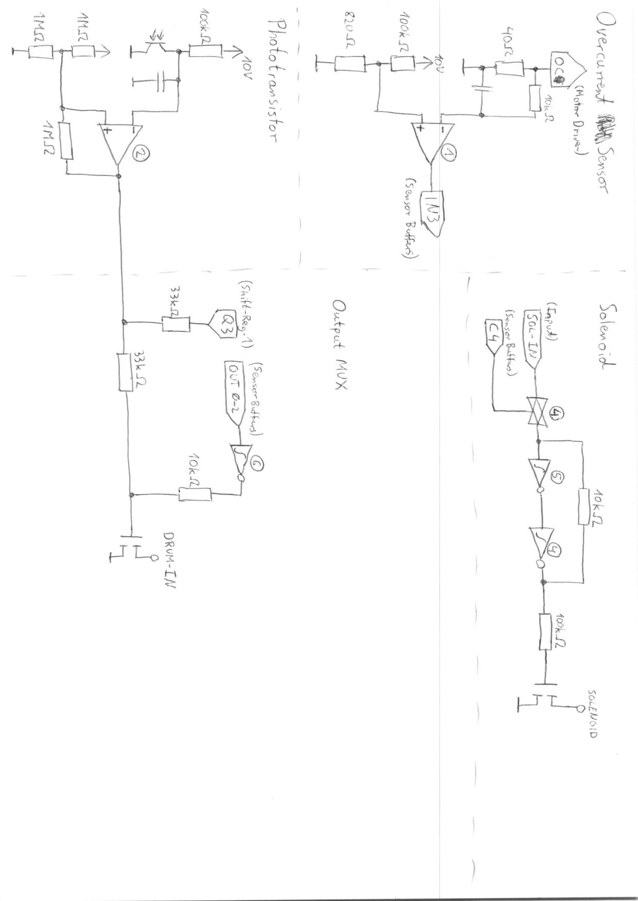
- The two cascaded Schmitt triggers in the solenoid control part, combined with the analog switch (which goes to hi-Z when disabled) implement a latch
- We think the part named "Output MUX" implements the function (Phototransistor ∧ Q3) ∨ (other outputs). This is rather weird.
- Who needs voltage regulators? They built their own and abused the IR LED of the light barrier for its voltage drop, too.
Next up: Implementing the control protocol to test whether things actually work the way we expect them to work.